Note: I haven't used Bryce in years; so these tutorials are archived "as is." I can't accept questions, because I don't remember the answers.
This is page 2. If you haven't finished page 1, please do so before starting this page.
 One more example of the Power of Math. One of the things that you are likely to find yourself animating, if you do much animation, is wheels rolling along the ground.
In order to look correct, the rotation on the wheel has to match the distance traveled. In other words; if you marked the edge of the wheel, the 1 inch mark should touch the ground when the wheel had traveled 1 inch. The 2 inch mark should touch the ground at 2 inches, and so on.
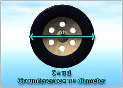
Each revolution of the wheel should carry it forward the length of its circumference.
Once more, what we learned way back in High School will answer here. If you remember, you can find the circumference of a circle by using the formula C= π d, where C is the circumference, and d is the diameter.
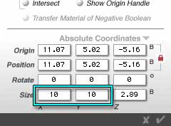 So, for any wheel, just open the Object Attributes, and find the diameter. (It will be the two numbers that are the same, of course.)
Then, just grab the calculator, and multiply that number by the value of π to find the distance it should travel for each revolution.
Let's actually do one, to make it clearer.
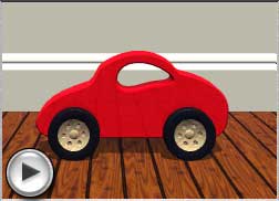
Load the Toy Car.obp included in this week's download. Select a wheel, and open the Object Attributes. You will find that the diameter of the wheel is 10 B. Multiply that by π to get the circumference. (If your calculator doesn't have a π key, use 3.14159) The answer is 31.4159, call it 31.416 B.
So, for every 360° around, the wheel should travel forward 31.416 B.
 Rotate the camera, so you are square to the world facing South, and I'll show you a trick. Because these are wheels, and there are four of them which all have to rotate the same amount every time, we aren't going to rotate any of them. Well, not directly, anyway. Instead, we are going to set up a null object, and rotate that.
Then we'll just set up the four wheels to use the null as a parent, with Rotation and Offset propagated, and it will all be done at once!
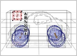
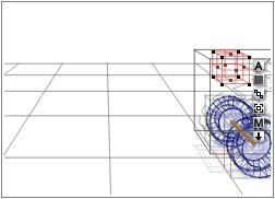
Create a cube (so you can manipulate it from any angle,) name it Wheel Parent, give it the Null material, shrink it, and position it above the hood of the car, where it's easy to get to.
 Because of the idiosyncrasies of Bryce, before you can choose the Wheel Parent as a parent, you have to ungroup the car. Bryce won't allow anything to have more than one parent, and it considers a group a parent.
Because of this, if we want the wheels to move along with the car (and I do, at least) we will also have to group the Null with the car chassis and axles. That way, when we move the car, the Null will go along with it, and the children of that null will follow it. I've already grouped the chassis and axles, and named the group Toy Car Body G, to save a little work.
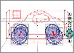
So, ungroup the car, and then select the Wheel Parent and Toy Car Body G, and group them. Name the group Moving Car Body
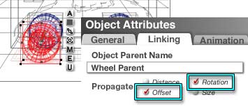 Select each Wheel Group in turn, open its Object Attributes, go to the Linking tab, and choose Wheel Parent from the drop down menu. Disable Distance and Size Propagation, but leave Rotation and Offset enabled. This is because we don't want to change the Size, so we won't need that one. If we left Distance enabled, the wheels would revolve around the Wheel Parent, as well as rotating, and we don't want that, either.
This combination will work perfectly, as long as we don't try to rotate the car. We won't be able to do that. I'm sorry, but if you need to rotate the car at all, the best you can do is group the wheels to the axles, and move that way. That will cut the numbers of keyframes in half, but it's the best we can manage in Bryce. (And it's why I kept the axles separate.)
 Make sure you are at Frame Zero, and place the car at the right side of the screen.
Make sure Auto Key is disabled, and create the first keyframe for Position on the car, and rotation on the Wheel Parent. (We may as well make them both, since we are here.) If Auto Key was enabled, destroy every key frame in the document by holding down Command+Option+Shift on a Mac, or Ctrl+Alt+Shift on a PC and clicking the Remove Keyframe button. Say OK to both the dialog boxes that will pop up, (as if you had a choice,) and all the keyframes will be eliminated, allowing you to start fresh without all the clutter.
We want the wheels to rotate smoothly. Remember that Bryce doesn't keep track of total rotation; just of the beginning and ending points. So, in order to rotate the wheels the way we want them to move, we are going to break that rotation up into 4 equal parts of 90°.
 Move the scrubber ahead in time 7 frames, make sure the Wheel Parent is selected, and open its Object Attributes. All the rotations should be at zero. Type -90 into the Z rotation field. (We are using negative rotation, because we want the wheel to move counter clockwise since the car is going from right to left.) Make a Rotation keyframe.
Move ahead in time another 7 frames, and type -180 into the Z rotation. Make another keyframe. Move ahead another 7 frames, and type -270 into the Z rotation text field. Make another keyframe. Move ahead another 7 frames, and open the Object Attributes for the fourth time. You will notice that the field where you typed -270 now says 90. That's what I mean about not taking into account the amount moved; just the final rotation. Because of that, 360 is equal to zero. So, type 0 into the text field, close the dialog, and make a final keyframe.
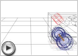
Play this, to make sure the wheels are going the way they should go, and that the motion is smooth.
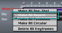 With the Wheel Parent still selected, go into the Advanced Motion Lab. Hold down the shift key, click on the Wheel Parent name, and choose Make All Repeat. The Wheel Parent will now continue to rotate smoothly at this speed for as long as the animation runs.
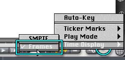 Let's make it three times as long as it is now, so the wheels rotate 3 complete times. SMPTE time is hard to calculate in these cases, while frame count is simple. So, go to the flippy triangle just past the AML, and set the Time Display to Frames. We are currently on frame 28. Three times that number is frame 84. So, set the scrubber to frame 84.
 With three complete revolutions of the wheels, the car should move 3 x 31.416 B, or 94.248 B. Call it 94.25.
Open the Object Attributes of the car, and add 94.25 to the number you find in the X Position field, so the car will move across the screen from right to left. Make a keyframe for car position. (Change your camera angle, too, if you need to. Don't forget to make both beginning and ending keyframes if you do.)
Run the preview, and you should see the car zipping across the screen, with all four wheels rolling exactly as much as they should to move it the distance it moves. As simple as that. (Well, maybe zipping is an exaggeration. Moving, anyway.) No trial and error, just a little math.
I'm sure that you can think of other places where math will be handy. Don't be afraid to use it; Bryce can handle it.
 Okay, we are going to leave all of this behind now, and I'll show you a few things about advanced Booleans and Multi-Replication.
You can accomplish amazing effects with booleans; but you have to group them properly, or they won't work at all. For instance, say you are making an aqueduct. (Thanks, Ellen, for posing this question in the first Bryce class.)
Create a cylinder, and rotate it on the Z axis so that it is horizontal. Open the Object Attributes, and resize it, so the dimensions are 20 B on the X and Z axis, and 10 B on the Y axis. This will be the outermost arch of the aqueduct.
 |
 |
We want to make 3 duplicates of this arch; two for decoration, and one to be the negative boolean that cuts through the others. The decorative arches should protrude slightly from this one, but have smaller diameters. And we want to be able to eyeball the whole thing.
So, duplicate this cylinder, hold down Option/Alt so that it will resize from the center, and pull it out on the X axis just as far as you want the inner arches to stick out past the ones above them.
Undo the operation, and open the Multi-Replicate dialog. There will be a number in the X resize text field; this is the percentage that you just resized the cylinder. Write it down, and click the X to cancel and close the dialog.
 |
 |
Make sure that you have undone, and that the duplicate cylinder is still selected, and once again hold down Option/Alt so that it will resize from the center, but this time grab a corner handle to shrink the diameter of the duplicate it to your taste. Undo, and open the Multi-Replicate dialog.
The percentage that you just used will be entered in the resize text fields on the bottom. Change the Y axis to the number you wrote down above, enter 3 for the number of copies, and tap the Enter key. You will have 4 perfectly sized, graduated cylinders, with the dimensions you eyeballed. (Yes, I know it doesn't seem to make sense that you resized the X axis, and the original number showed up there, but now when you multi-replicate it's on the Y axis; but that's the way it works. Try it the other way, if you don't believe me. It seems to use the Definition Coordinates when you resize from a corner.)
Select each cylinder, name them, and put them in different color families now. You will thank yourself later, when you want to select all the ones of a certain size to change the materials and so on.
 Select the original cylinder, and convert it into a cube using the Convert fly out on the Edit Palette.
Name it Top. Give it a rotation of zero on all three axes, and a dimension of 8 on the X axis, (so it will be a 1 B narrower on both sides than the arches,) 30 on the Y axis, (so it will be 5 B higher,) and 25 on the Z axis (So there will be 5 B of room between sets of arches.) Take a look at it, and pull the bottom up not quite to the half way point of the cylinders, so the bottom of the bounding box when it's grouped will be the cylinders, not this cube.
Choose a color family for the Top cube, too.
 |
 |
We need to make the innermost cylinder a negative boolean that will take the material away from all three of the other cylinders and the cube. At this stage, that's simple. Draw a marquee to select all the cylinders and the cube, and open the Object Attributes. A great deal of the information will be missing, because you are looking at the attributes of different things. Anything you change here will be changed for all the selected objects; anything you don't change will remain the way it was for each of them.
So change the Boolean properties to Positive.
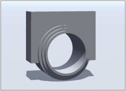 Then select just the innermost cylinder, change the properties to Negative, and group them. Do a test render now, and you will see a group of hoops, with a block thing straddling them.
Land the group, and call it Arch Hoops. Give the group a Positive Boolean attribute.
 Create a cube to use for the negative boolean that makes the hoops into arches.
Give it the dimensions of 15 on the X axis, (to be sure to cover all the arches,) 10.1 B on the Y axis (to make it cut the arches off at the halfway point, and a tad extra to cover,) and 25.1 B on the Z axis (the size of the Top cube, with a little extra for cover.)
 Select both the cube and the group, and align them on the X and Z axis. Select only the cube, land it, and then pull it down the slightest bit so it cuts the arches at the proper point.
Name the cube Arch Cut, and give it a Negative Boolean.
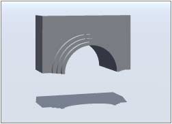 Group it with the Arch Hoops, which has a Positive Boolean as a group, and it will cut the group off at the middle of the arches. Name the group Arches. Now, if you render, you will see the arches.
Move on to Page 3, and we'll put the arch up on a column.