Note: I haven't used Bryce in years; so these tutorials are archived "as is." I can't accept questions, because I don't remember the answers.
This time, we are going to learn about making more complex objects out of simple primitives and importing objects made in other programs. We'll also start using the Materials Lab to make your own materials for shading and texturing. You will need to download Lesson2.sit or Lesson2.zip which has the necessary files (mentioned later) if you want to follow along.)
Shall we begin?
Please open Bryce, if it's not open already.
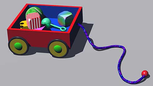
We are going to make a little wagon pull toy, and put some simple toys inside of it.
 Click on the title to open the Create palette. Click on the blue cylinder shape to create a Cylinder in the center of your workspace.
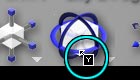
 Place your cursor on the Control Handle on top of the cylinder. It should change to a square with the letter Y in it, to show that you are about to resize the cylinder along the Y axis.
Click and drag, to make a flattened shape, something like this. This is the base for the wheel.
 Go to the Rotate Tool (on the Edit palette.) We need to stand the wheel on its side, since wheels that are flat on the ground don't do much good. In order to do that, we need to rotate it on one of the axis, so that it ends up with the flat side to our right. Which one should we use?
If you said, "The Z axis," you are correct. Remember, the Y axis is the vertical one. Rotating on that will just spin the wheel in place in its current orientation.
The X axis runs from side to side. Rotating on that one will make the wheel upright, but it will be facing the wrong way.
Rotating on the Z axis, which is the one that goes from front to back, will put the wheel in the correct position.
Move to the Rotate tool, hold down the shift key, and rotate along the Z axis. (Remember, the cursor will change to a square with the letter Z when you are about to manipulate that axis.)
Holding down the shift key constrains the movement to 45° increments. It's the easiest way to get the wheel exactly upright.
 Create a torus by clicking on the blue torus (doughnut) shape on the Create palette.
This will be the tire. But we have to make the two shapes align. In order to do that, we need to spin the torus so it's in the same orientation as the wheel. Which axis do we need to rotate around?
 If you said, "Y" you are correct. We need to move it on an imaginary, vertical line. Hold down the shift key, and do so. Keep an eye on the Nano-Preview to make sure that you are moving it in the right direction.
 Alright. They are both facing the same way, but are not aligned. We need them to align perfectly, on all three axis; so select both shapes, go to the Align Tool in the Edit Palette, and click on the blue dot in the middle to align them along all three axis. Good. But the balloon part of the tire is way too large.
 Click on an empty area to unselect everything.
Change to the Right Orthogonal view, so we can see the actual relative sizes of the two objects. Zoom in if you need to. Click the torus to select it, go to the Resize Tool, and click on the central cube part of the Tool to resize keeping the proportions. This also causes your object to resize from its center. Make the torus just a little larger, so the cylinder is contained inside of it.
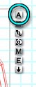
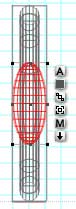
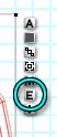 Now we are going to start using the Icon Column that shows up when you select something. At the bottom of the list is an icon that is a white square with the letter E in it. That stands for Edit, and is how you change the shape of tori. Click on it.
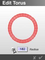 A little Edit Torus dialog will show up, with a preview of the torus, a button with a double headed arrow on it, and a text field labeled "Radius."
You can change the radius of the ring that forms the torus by either clicking and dragging on the button, or typing the number you want into the text box. As you click and drag, you will be able to see the preview change. Try it now. We are aiming for around 100 as the radius for this torus. When you've got it, click the check mark to close the dialog box, and keep the change.
You can also hold down the spacebar and drag to keep the diameter of the donut part constant, while changing the diameter of the whole ring. If you want to view it from other angles, you can click on Caps Lock, and it will automatically spin; or you can hold down Control/Ctrl and drag to change the angle yourself. Go ahead and play with those, but cancel out when you are through, because we don't want to keep any of those changes.
 We are going to name these two parts before we go any farther.
Your torus should still be selected. The first icon on the Icon Column is a little white square with a black letter A on it, which stands for the Attributes of the object. Click on it.
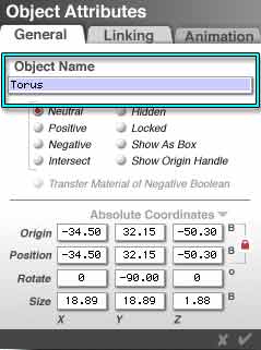 The Object Attributes dialog opens. The first field is Object Name. Changing the name of objects makes them much easier to find in complex scenes, and is a good habit to get into. Change the name to Wheel Tire, because that is what we are making. Just type it into the text field. Ignore the rest of this dialog box for now. We will be getting to each of these things later. Close the box by clicking on the checkmark.
Select the cylinder, and name it Wheel Base.
 Alright. Lets add one more part to the wheel, before we call it built.
Create a sphere. (Click on the blue Sphere in the Create Palette.) Name it Wheel Hub.
Resize it, using the corner Control Handle, so it's a half to a third the size of the wheel base.
 Switch to the Front Orthogonal view. Zoom in if necessary. Drag the sphere so the center more or less aligns with the center of the two other wheel parts. Now, hold down Option/Alt and use the Control Handle on the side of the sphere to squish it down along the X axis. Holding down Option/Alt makes it resize from the center, so it stays in line. You want it to stick out on both sides about the right amount to make a wagon wheel.
When you are happy with it, select all three objects, and align them along all three axis. (That's the blue button on the Align Tool on the Edit palette, remember.)
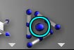
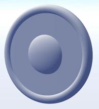 Do a quick test render, to make sure it's right. I recommend using the Director's View, set to Center on Selection, for this. (Remember? That's the third flippy triangle.) Move the camera as necessary to get a good shot. You want something like this.
Don't hesitate to resize the central cylinder if it projects beyond the torus anyplace.
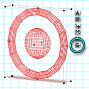 Got it? Good. Select all three objects. (Make sure you don't accidentally select the Camera. It should remain blue. If it's red, Shift-Click to unselect it.)
Notice that the Icon Column now has an additional icon on the bottom. That one is the letter G, and stands for Group. Click on it to group all the parts of the wheel, so we can treat them like a single object.
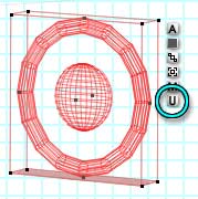 Notice that the bottom icon now is U. That, of course, is for Ungroup. You would click it to open the group, and treat the objects like three separate things again.
Open the Object Attributes, and name this group Wheel. Close the box by hitting the Return or Enter key.
 Now we need the body of the wagon. Create a cube. (Click the blue cube on the Create palette.) Name it "Wagon Body."
 Click on the Control Handle in the middle of the top face, so that your icon changes to a black square with the letter Y, and resize on the Y axis, to flatten your cube, so it looks like the proportions you would expect for a pull toy wagon.
Alright. We have a wagon, and one wheel, but the wheel is way too big!
 Go to the Right orthogonal view, so you can see its true size in relation to the base. Then use the Corner control handles or the Resize tool to shrink it until it looks like a wheel that might belong on the base, if the base was a little pull toy wagon. It resizes as a single unit, because it's a group.
Now, still in the Right orthogonal view, drag it to reposition it, so that it's in the right spot to actually be a wheel.
Copy it using either the menu or Command/Ctrl C, and paste using the menu or Command/Ctrl V. This will put a second wheel in exactly the same position.
Drag the second wheel over to make the second wheel of your wagon. It should look something like this.
 Alright. We want those two wheels to be exactly the same height, so we will have to line them up.
You already know, from the last lesson, how to align objects. Now I'm going to show you how to align them if the position is critical, and one is already perfect.
Ordinarily, when you use the Align Tool, it repositions both objects. But you can lock one so that won't happen.
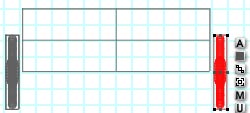
Open the Object Attributes dialog for the new wheel. Remember, it's done by clicking the A in the icon column that appears when an object is selected
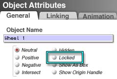
The name of this object is Wheel 1, because it's a copy of the object called "Wheel." (That's why you named it before you copied it. You only have to name it once, that way.)
Under the name is a list of attributes, with buttons you can check. The second choice in the list on the right is "Locked." If you click it, the object cannot be changed in any way. Click it now, and then click the check mark to close the box, and accept the changes.
 Then, while it is still highlighted, Shift-Click on the other wheel. We need to align them on one of the axis. Which one? If you said, "Y" you are correct. The Y, vertical, axis is what we need. So click the middle band of the Y cylinder in the Alignment tool on the Edit palette to align the center on the Y axis.
Ordinarily, you would unlock the locked wheel now, while it was still selected. But I want to show you something.
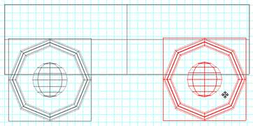
Click anywhere to deselect. Notice that the wheel you locked has a lighter gray wireframe than the other one. That shows that it's locked. We need to unlock it now, and in order to do that, we need to select it.
If you try to click on it, you will see that you cannot. It's locked, so it can't be selected by clicking. This comes in really handy in complex scenes, when you find that you are constantly clicking on something, and selecting it, when you don't want to select or move it at all. Just lock it, and you won't be able to accidentally do either one.
But it's still easy to select.
The easiest way is to hold down the Control/Ctrl key, and select it from the list that pops up when you click the mouse over it. But I want to show you a different way.
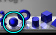
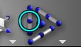
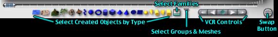
At the bottom of the screen is a row of bitsy icons, representing all the different kinds of primitive shapes and lights. This is the Selection Palette. You can select anything in your scene from here. (If you don't see them, click on the circle with the grid on it that you will find in the bottom right corner of your screen. That's the Swap Button, and it toggles between the Selection Palette, which we are about to use, and the Animation Controls, which are for the next course.)
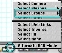 There is a flippy triangle at the right hand end of the row. Click on it, and a pop up menu will appear, giving you a choice of several things you can select. The wheel is a group, so you want to choose "Select Groups..." The pop out menu there shows all the groups currently visible in your scene.
Those are now named Wheel and Wheel 1. (See why we named them?) Select the name for the one you locked. That object is now selected, even though it's locked. Open the Object Attributes. There should be a red checkmark next to Locked. Click on it, to make it go away and unlock the wheel. Close the Attributes.
 Alright. You now have two wheels, exactly the same height; but they are in the center of your wagon, not on the side. We need to move them.
Select them both, either by shift-clicking or drawing a marquee, and group them by hitting Command/Ctrl-G on the keyboard.
Change to the Front orthogonal view, so you can position the wheels correctly along the Z axis.
Select the wheels object, and drag it to one side of the wagon.
Now, type Command/Ctrl-D. This duplicates the object that is selected, and places the duplicate right on top of the original object. It's like the copy/paste we used before, but faster. The new set of wheels will be selected. Drag them to the other side of the wagon. Be sure to leave a bit of room on both sides, so they can turn.
Then go on to Page 2