Note: I haven't used Bryce in years; so these tutorials are archived "as is." I can't accept questions, because I don't remember the answers.
In this final lesson, I'm going to go over a bunch of stuff that I think is really fun, and that I'd like to share with you, but that didn't seem to fit in any of the other lessons.
If you want to follow along, you'll need the files in LessonI-6.sit or LessonI-6.zip.
 A while ago a bunch of us were trying to figure out how to catch a reflection in a pane of glass. We knew the camera angle we wanted, and we knew exactly where the glass was. What we didn't know was where the object needed to be placed in the room so that the reflection would show up where we needed it.
It turned out to be fairly simple.
In optics, reflection is a change in the direction of a light ray as it bounces off a surface. If you draw a line perpendicular to the surface, that line is the Surface Normal. The angle made by the light ray and that normal is the Angle of Incidence. The Angle of Reflection is equal to it, but occurs on the other side of the Surface Normal, as shown above.
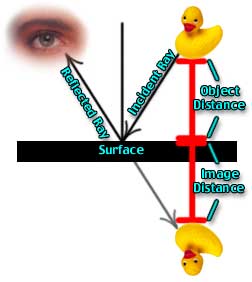 In order to see any object, whether reflected or viewed directly, you have to have a clear Line of Sight. This is true, because light travels in a straight line from the object to your eye. When you are viewing a reflection of the object in a flat reflective surface like a mirror, the ray of light going from the object to the reflective surface is known as the Incident Ray. The ray going from the reflective surface to your eye is known as the Reflected Ray.
If you project the angle of the reflected ray back through the mirror to the image, you will see that the apparent distance from the surface of the mirror to the reflected image (known as the Image Distance) is exactly equal to the actual distance from the object to the mirror (known as the Object Distance.) This equality holds true for all plane mirrors. Image Distance = Object Distance.
Knowing that, it's pretty easy to set up a scene in Bryce to take advantage of the fact.
 |
 |
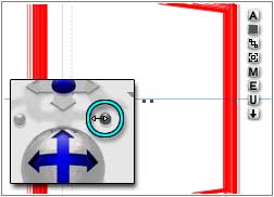
| Change FOV from Camera View | Until the Triangle is inside the Mirror; Top View |
First, set up your mirror, window, or whatever you want the reflection to bounce off of. For this exercise, we are going to use the Mirror.obp that was in this week's lesson. Create a room however you would like to make it (four flattened cubes as the walls, a cube with a cubical hollow booleaned out of it, or whatever you like the best.)
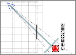
Put the mirror on a wall, and arrange the camera to form a pleasing angle with that mirror. Drag left on the Field of View button to give yourself a small camera angle, so that you can't see the wall past either edge of the mirror. You have to change it from the Camera view; but it should look like the figure above from the top. (It will just look like wall from the camera at that point, of course.
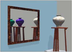
 Now, load the Occasional Table.obp. We need to catch the reflection of that table in the mirror.
First, we are going to place the Image, and from that we will know exactly where to place the object.
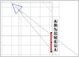
So, switch to Top view, and place the table within the perspective Field of View (FOV) shown as a dotted triangle projecting from the blue Perspective pyramid. (If you cannot see it, select the Perspective, open its Object Attributes, and enable "Show FOV.") If you want it to be in the center of the mirror, place it on an imaginary line drawn from the point of the FOV and perpendicular to the base. If you want it off center, place it on either side of that line.
Eyeball the distance from the wall; we can adjust that later if we need to.
 Got it? Good. We need to make an object, too; and it has to be the same distance from the plane the mirror sits in as the image. (Remember, Object Distance = Image Distance.) To get that as easily as possible, create a cube.
Still in the Top view, drag it over until the edge touches the edge of the table's bounding box. Then drag it out along the axis that is perpendicular to the plane of the wall the mirror is on. (In this case, the X axis.) Drag it until the edge is just past the inner edge of the wall; it should be in the same plane as the mirror's surface.
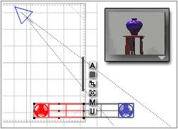
Group the table and the cube, duplicate the group, and flip the duplicate on the axis you used in the step above (the X axis for me.)
Drag the duplicate until the edges of the two cubes meet. If you look at the Nano Preview, you will see the table appear in the mirror (assuming your Nano Preview is set for Camera view. If it isn't, please make it so.)
 |
 |
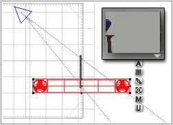
| Extreme Edge of FOV | Edge of FOV interrupted by wall |
Constrain the movement along the axis perpendicular to the one you used in the two steps above (Z in my case) by holding down the correct key on the keyboard (x for X, of course, and z for Z) and move the group. Notice that when it leaves the FOV cone, you can no longer see the reflection. (Of course, if it sinks through the wall, you won't be able to see it either. Try removing the walls, if that's a problem; you will see that anywhere in the FOV triangle is good.)
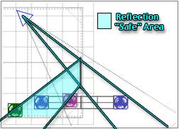
If the Image is within the FOV, so that there is a Line of Sight between the Image and the Camera, the reflection is visible in the mirror. If it's not, it's not.
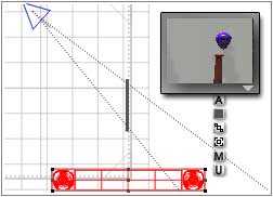
| Anything in the Reflection "Safe" Area will be reflected in the Render | |
 |
 |
This is subject to the size of the mirror, of course. Return to Camera view, and drag right to increase the FOV until you can see a pleasing amount of wall on both sides of the mirror.
If you drag the compound object now, you will see that the actual area where the reflection is visible is only as large as the angles made by drawing from the point of the camera FOV through the edges of the mirror. In other words, the Line of Sight angles between the mirror and the camera.
Remember this principle. You can make the actual physical models like this for as long as you need to. After a while, you will be able to look at the top view, and draw the necessary angles in your head to see the object's "reflection safe" area.
Once you understand that, you will be able to tell from just looking at the top view where you will need to place objects to capture their reflections in any flat surface you want. (Curved surfaces, of course, follow different rules; but catching a reflection in them is usually not a problem, since their "reflection safe" areas are so very large.)
 Let's take a look at how using a little math can make things much easier in Bryce. (That's why the numerical controls are there, you know.)
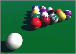
One of the things that math in Bryce can help with is the spacing of objects in the Multi-Replicate dialog. For example, putting balls on a pool table. Say you want to make a scene with the balls all racked, ready to shoot across the table. You could place them all by hand, which would take a long time and probably wouldn't look very exact. Or you could do it the easy way, using just a bit of math.
This uses the Pythagorean formula and a touch of algebra. (My thanks to Tom Shermer for figuring it all out, and explaining it all.)
 Take a look at this diagram. It shows three spheres, which all touch at the edges, which is the basis of we are going for. To use Multi-Replicate, which is what we want to do, we have to figure out how far to move them. Which means we need to know the distance from the center of one sphere to the center of the next, on the axis we want to move them on.
We'll assume the spheres have a radius of 1 B, just to make the math easy. That means that a line drawn between the centers of the two spheres marked one and two is 2 B. From Pythagoras, we know that when we are dealing with a right triangle the sum of square of the two sides is equal to the square of the hypotenuse. In other words, a squared + b squared = c squared. We know that a is one, and c is two. So a squared is 1, and c squared is 4. To write this out as an equation, 1 + b squared = 4; so b squared is obviously 3. The square root of 3 is about 1.732. (At least, that's more than accurate enough for Bryce, which only allows 2 decimal places.)
I've put all the algebra in the diagram above, which may make it easier to follow. The ridiculously accurate value for b is what was on my calculator. <g>
Translated into Bryce terms, that means the first Multi-Replicate should be offset by 2 on the X axis. That will give you a rank of balls going from right to left.
The second Multi-Replicate needs to be offset by 10 on the X axis (halfway between the balls of the first rank,) and by 17.32 on the Z axis.
 |
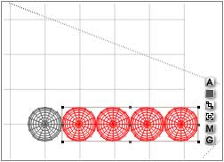 |
So, to make your nice neat rack of pool balls, all you have to do is make a single ball. Open the Object Attributes, and give it a size of 20. (We are going to multiply all of this by 10, just to keep the balls closer to Bryce normal size.)
Go to Multi-Replicate, and make 4 copies, offset by 20 B on the X axis.
 |
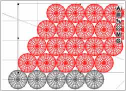 |
Select all five balls, and make another 4 copies, offset by 10 on the X axis (to get them centered between each of the existing balls) and offset by 17.32 on the Z axis.
 Then just remove the excess balls, and give the ones you are keeping the proper shading. Group them, and then resize or rotate as necessary. Your 15 pool balls are racked, and ready to go!
(Of course, if the math is making your head buzz, you can just copy these numbers down in a safe place, and simply plug them in when you need them.)
 |
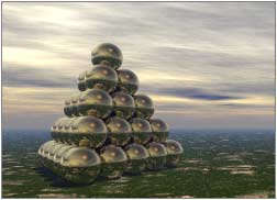 |
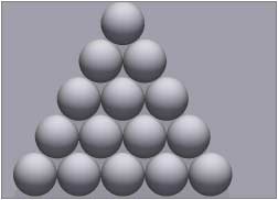
Which is great when you need things stacked in two dimensions. But what if you want them in three, like a pile of cannon balls? Once again, a little math and we will be on our way. Okay, more than a little; if you really want to see the math, it's in Appendix 1.
Otherwise, we'll just skip straight to the answer.
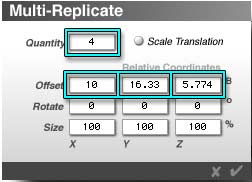
To make the 20 B diameter spheres stack, you need to Multi-Replicate them the first two times using the numbers above. The third time use 10, 16.33, and 5.774 as the values for the X, Y, and Z axis. Once again, just remove any excess balls when you have them stacked.
Now, of course, this can all be used for more than just spheres. You can stack a bunch of crayons to go in a box using the same method, or pile oranges in a grocery display, or anything else where you need a nice, neat stack of round things. And it's all done with only a few mouse clicks!
(If you have spun your balls to use as pool balls, and then you try this third Multi-Replicate, they will all replicate along their own X, Y, and Z axis. That's one of the odd things about Bryce Multi-Replicate; it seems to look at the object's definition coordinates most of the time. The solution is just to group them first, and Multi-Replicate the group. Its definition coordinates will be formed when you make it, and will be in the correct orientation to make the stack.)
Go on to Page 2 for another neat trick where a little math will actually save you time and effort.