Note: I haven't used Bryce in years; so these tutorials are archived "as is." I can't accept questions, because I don't remember the answers.
This is page 2. If you haven't finished page 1, please do so before starting this page.
 Once again, the wheels need to be aligned on the Y axis. We are going to use the numeric tools in the Object Attributes dialog this time. Select one set, and open the Object Attributes dialog.
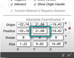
Skipping to the bottom of the dialog box, you will see, below the line, the Coordinates of the object. Currently, the Absolute Coordinates should be showing. Those describe exactly where the object is in Brycian Space.
If you click on the flippy triangle next to "Absolute Coordinates" you will see "Definition Coordinates." These describe how the object was created. You can change the attributes in these dialog boxes, as well, but it can yield unpredictable results since the Origin is always at internal 0,0,0. So we won't touch them in this course.
Make sure it says, "Absolute Coordinates."
Right now, the Origin and Position are locked together. You can tell, because there is a little red padlock to the right of them. That's what we want at the moment, so leave that alone.
We are going to change the position. The origin will change automatically. Alright, we need to make sure the wheels are in the same position on which axis?
Yes, the Y axis, the vertical one. So copy or memorize the information in the Position Y text box. Mine says 21.60, but what yours says depends on where your wheels are. It might be a lot different for yours.
Close this box by clicking on the X to cancel, select the other wheel, and open its Object Attribute box. Paste or type the value into the Position Y text box here.
Click the checkmark to close the box and accept the changes.
You will see your wheels move to match the other set.
 Great! Now we have two sets of wheels, but they are probably not aligned perfectly front to back and side to side with the body of the wagon. We can fix that easily, though.
Go to Director's View, so you can see a perspective view of the wagon. Select both sets of wheels. Notice that now both the Group and Ungroup icons are showing in the Icon Column. Clicking the U will dissolve both groups of two wheels. This will save on render time, because Bryce checks all groups in the path of each ray. If there are extra groups in that path, it means extra render time. Clicking U again will dissolve each single group that makes a wheel, too. But we won't do that, because we might want to move them again as a group. As with everything, it's a tradeoff. Click the U exactly once now.
Then click the G to make a group of all four wheels.
 Now, we want to center the wheels and the wagon body on two of the axis, but not the third. Know which ones we will need to align? If you said, "X and Z" you are correct.
Use the Align tool to do this. (Select both the group of wheels and the wagon body, and then click on the middle blue bands for the X and Z axis of the Align Tool.)
 There! A wagon with four wheels. Open the Object Attributes for the Wheel group, and give it a name. (Something like Wheel Group makes sense, but you can call it anything you like. Putting "Group" in the name makes it easier to tell that you are about to select the group, not an individual object, when you are selecting things from a list.)
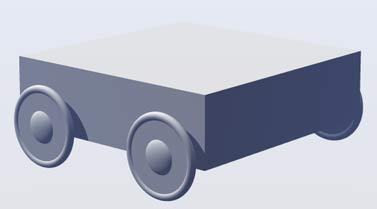
OK. Time for a quick test render, just to make sure everything looks the way it should. (Don't forget to save, too.) Hit the Render button. You should have something like this.
Looks a little gray, doesn't it? Let's fix that.
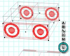
![]() First, we want to select all the Wheel Bases, and only the Wheel Bases. Fortunately, that's easy to do. Go to the Selection Palette at the bottom of the screen, and click on the tiny icon of a Cylinder, because the Wheel Bases are all really Cylinders. As you see, there is a pop-up menu that allows you to choose all of the type, or each one individually by name. (See why we named them?) We want them all, so choose Select All of Type. They are all selected, as you can see.
First, we want to select all the Wheel Bases, and only the Wheel Bases. Fortunately, that's easy to do. Go to the Selection Palette at the bottom of the screen, and click on the tiny icon of a Cylinder, because the Wheel Bases are all really Cylinders. As you see, there is a pop-up menu that allows you to choose all of the type, or each one individually by name. (See why we named them?) We want them all, so choose Select All of Type. They are all selected, as you can see.
(If you don't see this palette at the bottom of your screen, click on the Swap Button (far right above) to get it.)
![]() Now, click on the M in the Icon Column. This opens the Materials Lab.
Now, click on the M in the Icon Column. This opens the Materials Lab.
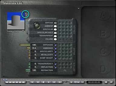 It's a pretty complex place, so we are going to just ease into it a little bit at a time. In the upper left hand corner, you will notice a preview picture, just like the one you were using during the last lesson to preview the Preset materials. Just exactly like it, in fact; because this is the same one, only in a slightly different place.
To the right of it is a flippy triangle. Click on it.
The familiar Materials Preset will open. Go to the Simple&Fast category, and click on "Shiny Red Plastic" to select it. Click the checkmark to close the dialog.
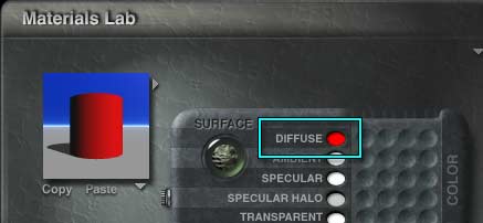 Now, to the right of the preview, you will notice a grid with words on the left and little dimples in columns on the right. The top row is labeled "Diffuse." This is the color that your object will be where direct light hits it. Right now, it's red, because you have chosen red plastic.
 But we want the wheels to be some other color. So hold the mouse button down on that red swatch. The simple Bryce color picker shows up. Your cursor changes shape to look like an eyedropper. That means you can pick up a color. Slide along the color picker, keeping an eye on the swatch as it changes color, until you have a color you like for the wheels. (I made mine yellow.)
When you like it, release the mouse button. See? The color changes in the preview.
Click the checkmark to close the dialog and keep the new color. You can see how it looks in the Nano-Preview.
Select each part, in the same way, and give them all colors. Remember, the tires are tori, the hubs are spheres, and the wagon body is a cube.
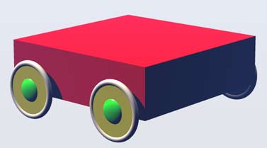 Render again. You should have something like this, although your colors are likely to be different.
Alright, that looks like a pull toy, maybe, but where is the opening in the wagon? Well, there are several ways we could make it. But the one we are going to use involves a very special Bryce tool, called a Boolean.
Booleans are used to combine shapes with other shapes. There are three kinds of Boolean operations in Bryce.
The one we are going to use now is Boolean Subtraction, where we will take one shape away from the other.
 Make another cube. (Click on the Cube in the Create palette.) Give it a name, like Wagon Inside.
Align it with the first, and make it smaller on the X and Z axis. Just use the Resize Tool on the Edit palette to shrink it proportionally from the center, and keep it aligned. (The height of the Y axis isn't important, as long as it is higher than the wagon itself. You can squish it down if you like.) Check it using one of the Orthogonal views to make sure it's right, and resize some more if necessary. Move it around until the space between the sides and the bottoms of the two cubes are about the same. Select all three pieces and align on the X and Z axis to make sure it's all still centered.
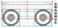
It should look something like this, from the Right view. From the top, of course, the smaller cube should be nested perfectly in the larger one; but that is automatic with proportional resizing and use of the alignment tool.
 We are ready to Boolean. Select the wagon body, and open the Object Attributes. Now, in the first column of attributes on the left, you can choose Neutral, Positive, Negative or Intersect.
These are the Boolean attributes of the object. Neutral means that it won't be affected by Booleans at all. Positive means that this will be the Positive half of a Boolean subtraction or intersection; the part that other parts will be subtracted from. Negative means it's the part that will be taken away from other parts. Intersect we will get to later.
Click next to Positive, because we are going to be taking a chuck out of the wagon body, and leaving the rest.
Close the dialog box.
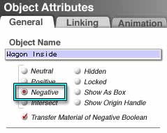 Now, select the Wagon Inside, and open its Object Attributes box. Click the Negative attribute, because this is the one we are going to use to take away the inside of the wagon. Think of it as the Antimatter, eating away all the Matter from the Positive stuff. (But without the explosion, of course. Quiet, civilized Antimatter.)
You will notice that Transfer Material of Negative Boolean becomes active, and is checked by default. Leave it like that for right now. Click the checkmark to close the dialog.
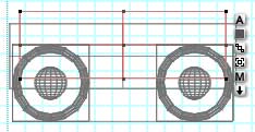
 Notice that the wireframe for the Wagon Inside is now showing as a dotted line. That lets you know it's a Negative object. Select both the Wagon Body and the Wagon Inside, and group them. (Click the G in the Icon Column.) Keep an eye on the Nano-Preview as you do this, because it's fun to watch. (It's even better if the Nano-Preview is set to look at one of the Perspective views (Camera or Director's.) Remember how to do that? Use the flippy triangle below the preview.)
 Notice that the group bounding box has diagonal lines in the corners. That shows a Boolean operation occurring.
 Return to a perspective view, and render again. Ahh. A real wagon. It should look something like this. [02-07] A bit on the square side, perhaps, but I'm sure you can figure out how to fix that, if you want to! <g>
Notice that the inside of the wagon is gray. That's because the Wagon Inside cube is gray. If you select it, and change the color, you will see the inside color change, too.
You don't need to ungroup to select it. You can either choose it from the Selection Palette at the bottom of the screen (click on the cube icon there, and choose the one with the correct name) or Control Click and choose it from the pop-up list that will appear.
Change the color, and check it out!
 Alright. We have our pull toy. But where are the blocks to put in it? Lets make those, too.
Now, this is obviously for a really small child, so we want blocks with rounded corners. We'll make them by using the Boolean Intersect function.
We'll also use a trick that helps a lot in complex scenes, and actually construct our block in a different scene.
So, save this one, and open a new one. (You can only have one scene open at a time in Bryce.)
Create a cube and a sphere. Name them. (I used "Block Cube" and "Block Sphere," just to make it easier later.)
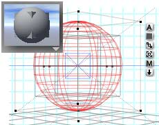
Select the sphere, if it isn't selected, and enlarge it using the Resize Tool (on the Edit palette.) Keep an eye on the Nano-Preview, and make it just big enough to knock the corners off the cube. (The parts showing beyond the sphere will be the parts that are removed.)
It should look something like this.
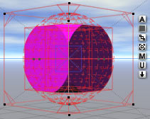
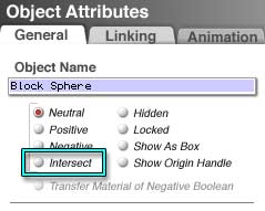 Now, while the sphere is still selected, open the Objects Attributes, and change the Boolean attribute to Intersect. This will cause the Boolean operation to render any part of the object that shares the same space with a grouped Positive object, and none of the rest of either object.
 Notice that the wireframe is now composed of dashed lines. That signifies a Boolean Intersect object.
 Select the Cube, and change its Boolean Attribute to Positive.
Select them both, and group them. Name the block, and give it a color (click the M to go to the Materials Lab, and either grab a preset, or change the diffuse color to get one you like.)
Save this file, because if you have all the things you have made in separate files it makes it easier to find them and use them again in other scenes, and it makes you relatively Crash Proof. If the worst happens, and you loose your scene file, at least you don't have to rebuild everything from scratch. (Make backups, too, of course, and store them in a safe place.)
Copy the block, close this file, and continue with Page 3.